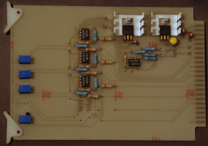
In the days before routing switchers, audio sources needing to appear on more than one mixer had to be “split” through one of a couple of means. The absolutely cheapest and worst method was to simply wire them up in parallel. Short circuits, insertion of patch cords, and so on would hammer the audio to all destinations. The method in place in the early years of RTVF was an RCA “MI” part number passive resistive divider. These were packaged in nice small metal cylinders with solder terminals on the phenolic base. Several problems here. First, we had a mix of balanced and unbalanced signals. The resistive pad/ladder arrays in the dividers responded differently to high impedance, low impedance, balanced, and unbalanced sources/loads. Worse, the RCA BC-7 mixers used +8 dBm for standard output (so did the quad machines) other mixers used +4, and of course the industrial/pro-sumer gear was -10. We needed Audio Distribution Amplifiers.
Several engineering building-blocks were simply never available in the “donation market”. Waveform monitors and vector scopes were impossible to find “for free”. Following along behind the scopes were video and audio distribution amplifiers and patch panels. These items were expensive and virtually never showed up even at Maryland Surplus Property.
During the late 70s / early 80s, experts such as Walter Jung and others published I.C. “cookbooks”. These were engineering publications that offered in-depth analysis of commercially developed integrated circuits and contained generic schematic diagrams of suggested applications. National Semiconductor, Motorola, and Signetics all published excellent product specification manuals. The 5532 chip was cheap, had very good performance, and could drive a balanced audio load to very high levels at low distortion, so we decided to make our own audio distribution amplifiers.
As in the past, we submitted a work order to the excellent folks at the Physics Department. We provided a rough layout and our schematic, and the Physics department manufactured a blank circuit board per our specs. We specified gold plated card-edge contacts and edge connectors to keep things “quiet” and used an off-the-shelf Vector brand enclosure for our boards. Each board had a master gain, and trim gains for each output.
As in the past, the interns stuffed the circuit boards with the parts, soldered them in, and participated in testing their product. I made my one request: where possible, install the resistors with the color code facing the same direction, mount components with alpha characters such that you can read them with the board oriented “up”. The above picture is a board I kept as a souvenir. Note that board was laid out as a 1 by 4. Despite the low cost of the parts, we stuffed this one for three outputs. I can’t recall why.
